Motor Car Exhibition at Olympia
Another completely new car exhibited is the 10 horsepower BSA.
This has an aircooled twin cylinder engine of the 90 degree V pattern, and the cylinderdimensions are 89.75mm bore by 85mm stroke.The body is designed to carry twoadults, but there is room for a third in emergency, the front seat being 3ft 6in wide,and there is a dickey seat at the back. We propose to give further particulars ofthe mechanical features of this car in our next issue.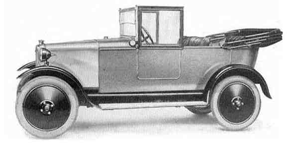
The 10 horsepower car built by the Birmingham Small Arms Company, to whichwe referred in our last issue, is a distinct departure as regards its mechanicalfeatures from this firm's standard practice. It also possesses originality as regardsthe design of the body. The great objection to the ordinary dickey seat - that inhad weather its unfortunate occupants are left exposed - has been overcome in thiscase by a hood of ingenious design which can be extended to cover the dickey seatwhen necessary. When the dickey seat is unoccupied, the hood is of the ordinarytwo seater form, and with the side curtains provides complete protection from theweather. Should the dickey seat be occupied, however, the extension of the hoodis only the work of a few minutes. There is also a fair amount of space for luggagein the tail even when the dickey is occupied, while with the dickey seat unoccupiedthe luggage space is very considerable, as, in addition to space inside the tail, theflat sloping top is covered with ribbed aluminium and is adapted for use as aluggage grid on which quite large articles can be carried.
With regard to the motive mechanism, there is nothing in the outer appearance ofthe car to give any suggestion that the mechanism differs from that of an ordinarycar. The engine is placed under the usual bonnet, and not even the cylinder headsare exposed. The whole of the air for cooling purposes is taken in through thedummy radiator, and passes out partly through louvres in the bonnet sides andpartly under the floor hoards. The engine is of the twin V pattern, with cylinders89.75mm bore by 85mm stroke. Sectional views of the engine are given in Figs 14and 15. The cylinders are of cast iron in one piece with the heads. There is apatented valve gear, whereby the radially inclined valves, which seat directly in thespherical head of the cylinder, are operated by rode lying parallel to the axis of thecylinder. The valves themselves are made of a new alloy produced by Wm. Jessopand Sons'Limited, and are tulip shaped. The cylinder walls and head are thick toprovide ample conductivity, and thus prevent distortion due to unequal heatconditions.The cooling fins are deep with roots of reasonable thickness, while thefins on the cylinder heads are so disposed as to equalise the temperature all over, and so prevent excessive temperatures in the neighbourhood of the exhaust valvescat and pocket. It is claimed that the inclination of the valves makes thecombustion space of almost ideal form, so that the flow of heat to the walls fromthe burning gases is as small as possible, while the turbulence of the charge is keptat the maximum. The aluminium alloy pistons are full skirted, as opposed to the'Slipper' type, so as to provide good dissipation of heat to the walls of the cylinder.By the insertion of a small spring ring at each end, the hollow floating gudgeonpins are prevented from moving axially and so scoring the cylinder walls. Both bigends, of course, work on a common crank pin, each big end being provided witha large diameter roller bearing. The crank shaft has balance weights, and is carriedby two hall bearings which are seated in cast iron housings and not direct in thecrank case, so that they cannot become loose in the aluminium.
At the rear end the crankshaft carries the flywheel in the usual way, while adjacentto the front bearing is the spur pinion which drives the half-time wheel on the camshaft. The latter is mounted directly above the crank shaft, the cams themselvesbeing inside the crank case, in the angle between the two cylinders. The four camswork direct on the mushroom ended tappets, which are prevented from rotating,and the tappets in turn operate the overhead valve rockers through the mediumof long hall-ended push rods. Each overhead rocker is completely enclosed bytelescopic tubes. The whole of the overhead valve gear is thus protected from dirt,and is lubricated automatically by oil mist sprayed up from the crank case throughspecial grooves cut for the purpose in the tappet guides. Tappet adjustment isprovided on the overhead rockers, and is immediately accessible by removing therocker case lids.
The ML magneto is gear driven off the half-time wheel on the cam shaft, and isprovided with a micrometer adjustment for setting the ignition timing. Themagneto contact breaker faces forward and is thus very accessible. An oil sumpholding sufficient oil for well over 200 miles' running is cast in one with the crankcase. Oil is drawn from this through a large filter by a submerged gear pumpdriven by the crank shaft through spiral gears and a short vertical shaft. From thepump oil is forced under pressure up a pipe leading to the wall of the near-sidecylinder, while small branch pipes cause jets of oil to impinge on the timing gearsand the magneto drive gears. An oil spray is thus formed which effectuallylubricates all hearings in the timing case. The off-side cylinder and piston arelubricated in the usual way by splash from the rotating crank shaft and big ends.Surplus oil from the crank case drains hack to the sump, while the sump itself isfinned to ensure that the oil is kept at the correct temperature. An oil flowindicator is fitted in a convenient place to show whether or not the lubricationsystem is acting correctly when the engine is running.
The starting handle is carried in an extension of the aluminium casting which formsthe timing case cover, and engages with a dog on the end of the cam shaft insteadof the crank shaft. Thus the engine is geared up from the starting handle, afeature which makes it easy to 'swing' the engine at a good speed without undueeffort. There is a special induction system, combined with the exhaustarrangements, which calls for attention. In this system a 'hot spot' is providedadjacent to the Zenith carburetter, which ensures vaporisation of the lowest gradefuels.
From the engine the power is transmitted through a double plate clutch of the corkinsert type to a three speed and reverse gearbox of conventional design, see Fig 16.This gearbox is bolted to the crank case, so as to form one unit with the engine.The clutch is completely enclosed in the fly-wheel pit between the engine andgearbox, but can be got at if necessary through an inspection door. The gearchange is operated by a centrally placed lever, mounted on a ball and socket jointin the gearbox lid itself. It should be noted, however, that contrary to usualpractice, when a central gear change is employed, the hand brake lever is notplaced in the centre of the car, but is at the right hand side of the driver, whereit does not obstruct the seats and cannot be interfered with by the passenger.From the gearbox the drive is taken to the rear axle by a tubular propeller shaft,which is completely enclosed in a spherical headed torque tube. Inside thespherical joint and completely enclosed by it is a ring universal joint, which isautomatically lubricated from the gearbox. This is the only universal joint on thecar.
The rear axle of the BSA car is of the built-up type, with a cast aluminium centreand steel axle tubes. It incorporates a Daimler-Lanchester worm gear, which issilent in action. Daimler-Lanchester worm gears have been a feature of Daimlerand BSA cars for many years, but this new BSA car is the first light car in whichsuch a rear axle specification has been included. A standard type of beveldifferential gear is fitted, while both hand and foot brakes are of the internallyexpanding type, operating in drums of unusually large diameter on the rear wheels.The brakes are of the non-compensated type, operated by rods throughout, and areprovided with means for instant adjustment by spring-locked wing nuts, situated inan accessible position. Another interesting feature of the brakes is that if it bedesired to inspect the brake shoes it is only necessary to remove the detachablerear wheels, when the brake drums themselves can be pulled off by hand and theshoes with their operating mechanism exposed to view. This is an improvement onusual design which necessitates the wheel centres being pulled off the axle shaftsbefore the brakes can be exposed, a job which, as most owner-drivers know, oftenrequires special tools not available in the owner's garage.
The front axle is of the usual I section forged type, but the stub axle and swivel pindesign is unusual, in that it is so arranged as to allow the swivel pin to be in theplane of the wheel. Thus no bending moment is caused on the swivel pins by theweight of the car or by road shocks, and, moreover, there is no tendency whateverfor the wheels to be deflected by road obstructions. This feature greatly reducesthe stress on the steering gear, and makes it possible to drive the car with thelightest touch on the steering wheel, even on bad roads, and in spite of the factthat the steering gear is not irreversible. The steering gear, front hubs, springshackles, brake rockers, are fitted with Enots grease gun fittings. Quarterelliptical leaf springs are fitted front and rear. The foot accelerator pedal andignition lever are on the steering column. An electric self-starter is fitted, andwhen the spark is fully retarded a special cam automatically opens the throttle tothe correct starting position.
 |